LADDER LEVELER INSTRUCTIONS
Do not use levelers if they cannot be mounted firmly.
Inspect levelers before each use
Warning: Dynamite Ladder Pro, LLC assumes no responsibility for leveler or ladder failure due to improper use, installation or maintenance. We do not assume responsibility for leveler or ladder failure due to our inability to predetermine the type, material or condition of the ladder on which the leveler is mounted. READ AND FOLLOW ALL INSTRUCTIONS CAREFULLY.
DOWNLOAD THESE INSTRUCTIONS
MOUNTING INSTRUCTIONS
Do not use levelers if they cannot be mounted firmly
Warning: Dynamite Ladder Pro, LLC assumes no responsibility for leveler or ladder failure due to improper use, installation or maintenance. We do not assume responsibility for leveler or ladder failure due to our inability to predetermine the type, material or condition of the ladder on which the leveler is mounted. READ AND FOLLOW ALL INSTRUCTIONS CAREFULLY.
Not recommended for use on fiberglass extension ladders with riveted rung-to- plate or rung-to-rail angle brace connections at the bottom rung unless leveler installation hardware will be accessible without disassembling either connection.
For use only on type II, I, and 1A aluminum and fiberglass extension ladders up to 32 feet.
(Required Tools: 2-7/16″ wrenches or sockets, drill with 1/4″ drill bit)
- Remove existing feet attached to ladder, if applicable or desired. Never disassemble a riveted rung-to-plate or rung-to-rail angle brace connection.
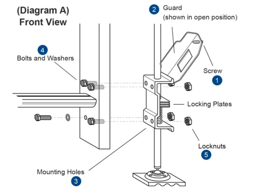
- Remove screw (1) from guard (2) and swing up to expose mounting holes in frame.
- Using Leveler as a template, center unit over bottom rung on outside of ladder side rail and mark location for four mounting holes (3). Leveler must be parallel to side rail.
- Drill four 1/4″ diameter holes through rail at location mark.
- Using bolts and washers (4) provided, attach unit to outside of ladder side rail as shown in (Diagram A). See stamped (R) & (L) on guard for correct right and left configuration. Bolts must face leveler and excess threads be on the inside of housing. The 1” bolts are for mounting to fiberglass and aluminum ladders only.
- Install locknuts (5) and tighten snug and securely with 7/16” wrenches. DO NOT OVER TIGHTEN
- Swing guard back in place and install retaining screw (1).
- Repeat steps 2-7 for opposite side of ladder.
Note: If bottom rung is more than 7″ from end of rail unit can be mounted below rung. In this case bottom two mounting holes should be no less than 1-1/2” from end of rail.
DO NOT use smaller or larger than the provided 1⁄4“ diameter 1” long bolt. For mounting to Metallic Brand Ladders use 8 Qty – SAE Grade 5 – Zinc 1⁄4”- 20x 2” Course Hex Bolts w/ 7/16” head (NOT PROVIDED). DO NOT use smaller or larger than a 1⁄4”-20x 2” bolt. Use supplied locknuts.
Note: When guard is in place, the company sticker should be facing the climbing side of the ladder.
OPERATING INSTRUCTIONS
Inspect levelers before each use
- Inspect levelers for missing, damaged, loose and corroded components/hardware. Over time vibrations from vehicle transportation may cause loose bolts/screws. Never use a damaged leveler and never make repairs. Check that the leveler is assembled to the ladder securely and is in good working order.
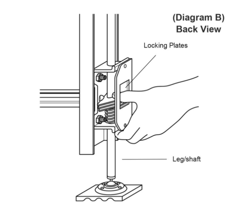
- Check operation of leveler. Make sure locking plates are working properly and firmly engaging leg/shaft and will not move when weight is applied.
- Keep leveler, leg/shaft and foot free of foreign materials such as lubricants, soaps, wet paint, mud, snow, sand, etc.
- Destroy ladder and levelers if exposed to fire or chemicals.
Proper set-up and use (See Diagram B) Back View
- Follow use and limitation instructions provided with your ladder. Always use ladder at proper 75 1/2-degree angle and never over or under that angle.
- Use on firm non-slippery surfaces only. Use at ground level only.
- DO NOT use both levelers in fully extended position to gain additional height.
- Fully retract both levelers before positioning ladder.
- After properly positioning ladder adjust the length of the foot, which is not touching the ground, by squeezing spring loaded locking plates with the thumb on plates and four fingers on lower bracket. This will allow the leveler foot to drop down to the ground. Release the locking plates to relock ladder leg/shaft and hold the ladder in a level position. DO NOT adjust leg height without squeezing locking plates.
Warning!Do not use leveler without checking for the correct position (See Diagram B) of the locking plates each time a new ladder set is made.